1.3.1
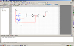
Combinational and sequential logic are the fundamental building blocks of digital electronics. Combinational logic, which is sometimes referred to as "combinatorial logic”, is characterized by its output being a function of the current input value. A variety of different logic gates can be used to implement combinational logic circuits. Many of these gates will be studied in future units of this course. In this introductory unit, we will limit our designs to AND, OR, and Inverter gates for the sake of simplicity.
In this activity you will use the Circuit Design Software to build and test your first combinational logic circuits.
Conclusion
1. From your life experiences, list 3-5 examples of products that you have used that contain combinational logic.
- Check engine light, computers, calculator, dual light switch, phone
2. Throughout this activity we used switches for the circuit inputs and a probe for the circuit outputs. Though this works fine for testing purposes, it is not practical for real-world applications of combinational logic circuits. List three input and three output devices that would be used with real world applications of combinational logic.
-thormometer
1.3.2
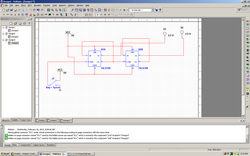
Along with combinational logic, sequential logic is a fundamental building block of digital electronics. The output values of sequential logic depend not only on the current input values (i.e., combinational logic), but also on previous output values. Thus, sequential logic requires a clock signal to control sequencing and memory and to retain previous outputs.
In this activity we will use the D flip-flop. We are limiting our use to this type of flip-flop in this introductory unit because of its simplicity and ease of use. The D flip-flop is just one of many different types of flip-flops that can be used to implement sequential logic circuits.
Conclusion
1. List 3-5 real-world applications where you might find counters like the one examined in this activity.
- dual light switch, Clocks, timer
2. Simple counters are just one application of sequential logic. From your life experiences, list 3-5 examples of products that you have used that contain sequential logic.
- dual light switch, Clocks, timer
1.3.3
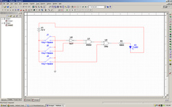
Just a few short weeks ago, most of you knew little or nothing about digital electronics. Now you are about to build and simulate a complete design. This design, the Board Game Counter, will be your first exposure to combinational and sequential logic, which are the basic building blocks of digital electronics and the topics of study for the majority of this course.
In this activity you will use the Circuit Design Software to build and test the complete digital logic section of the Board Game Counter design.
Conclusion
1. The combinational logic in Board Game Counter was AOI logic. What are three gates that are used to implement AOI logic?
- Not, And, and Or
2. On the 74LS74 D flip-flop, the CLK input has a small triangle. The PR (preset) and CLR (clear) inputs have a circle. What do these symbols mean?
- That there inputs where reverse before they entered the data pool.
3. What is the primary characteristic that differentiates combinational and sequential logic?
-sequential reads the combinational
1.3.4
Who fought in the Battle of Hastings in 1066? Who invented Silly Putty? Which of the Wright brothers flew first? All very important questions, but it would simply be impossible to keep all of the answers to such questions in your head. This is why we turn to the available resources like the Internet and textbooks to retrieve such information when necessary.
The same information overload is true when it comes to integrated circuits. What is the function of a MAN6760? How many pins does an LM555 Timer have? What is the maximum supply voltage for a 74LS08? All of this information and more is available in the manufacturer datasheet for each of these components.
In this activity you will learn how to obtain and extract information from the manufacturer datasheet for several components commonly used in digital electronics.
Conclusion
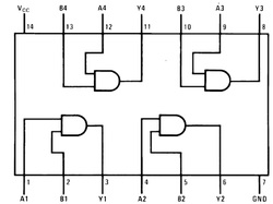
1. Using the datasheet obtained for the 74LS04 Hex Inverter Gates as a reference, answer the following questions:
What is the nominal Supply Voltage (Vcc)?
- 5volts
What is the maximum Free Air Operating Temperature (TA)?
- 70 degrees celsius
What is the typical LOW-to-HIGH Propagation Delay (TPLH)?
- 3min, 10min
What is the typical distance between two adjacent pins on a 14-Pin Dual-In-Line IC Package?
- .1
2. Who is Jack Kilby? What was his contribution to the field of digital electronics?
- integrated circuit
3/4. In the purpose section, you were asked (i) Who fought in the Battle of Hastings in 1066, (ii) Who invented Silly Putty, and (iii) Which of the Wright brothers flew first.
We can’t leave these questions unanswered, can we? The answers are; (i) England and France, (ii) James Wright, and (iii) Orville.
- MAN6760 - 7 digit
- LM555 - timer
- 74LS08 - and gate
Who fought in the Battle of Hastings in 1066? Who invented Silly Putty? Which of the Wright brothers flew first? All very important questions, but it would simply be impossible to keep all of the answers to such questions in your head. This is why we turn to the available resources like the Internet and textbooks to retrieve such information when necessary.
The same information overload is true when it comes to integrated circuits. What is the function of a MAN6760? How many pins does an LM555 Timer have? What is the maximum supply voltage for a 74LS08? All of this information and more is available in the manufacturer datasheet for each of these components.
In this activity you will learn how to obtain and extract information from the manufacturer datasheet for several components commonly used in digital electronics.
Conclusion
1. Using the datasheet obtained for the 74LS04 Hex Inverter Gates as a reference, answer the following questions:
What is the nominal Supply Voltage (Vcc)?
- 5volts
What is the maximum Free Air Operating Temperature (TA)?
- 70 degrees celsius
What is the typical LOW-to-HIGH Propagation Delay (TPLH)?
- 3min, 10min
What is the typical distance between two adjacent pins on a 14-Pin Dual-In-Line IC Package?
- .1
2. Who is Jack Kilby? What was his contribution to the field of digital electronics?
- integrated circuit
3/4. In the purpose section, you were asked (i) Who fought in the Battle of Hastings in 1066, (ii) Who invented Silly Putty, and (iii) Which of the Wright brothers flew first.
We can’t leave these questions unanswered, can we? The answers are; (i) England and France, (ii) James Wright, and (iii) Orville.
- MAN6760 - 7 digit
- LM555 - timer
- 74LS08 - and gate
