1.2.1
The Bohr model of the atom was introduced in 1913. It is an early representation of the atom often introduced in chemistry to describe energies associated with electrons based on their location to the nucleus in the atom. While newer models of the atom are more accurate, the Bohr model was instrumental in understanding how elements are placed on the periodic table, and the properties that an element has based its number of valence shell electrons.
The distribution of electrons in the orbital rings around an atom’s nucleus can help determine an element’s electrical properties. The stability of the electrons in the atom’s outer-most ring are one factor that helps determine whether an element will act as a conductor, an insulator, or a semiconductor. It is also important to look at the physical properties of the element when trying to determine which might be a better choice as a conductor, insulator, or semiconductor (state at room temperature, melting point, oxidation-reactivity with other metals). Cost and availability should also be considered. Combinations of elements can create new materials with desired properties that an element alone might not have.
In this activity you will use the Internet to research the atomic structure of materials commonly used in electronic applications. http://www.ptable.com/ is a resource that can be used to investigate the properties of some important elements in determining if they are good conductors, insulators, or semiconductors.
Conclusion
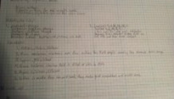
1. What are the three basic particles that make up all atoms?
-Electrons, Protons, Neutrons
2. What are some of the characteristic of an element that makes it a good conductor?
-Their valence electrons are few making the field empty causing the elements want change
3. Give three examples of elements that make good conductors.
-Copper, Gold, Silver
4. What are some of the characteristic of an element that makes it a good insulator?
-their valence electrons field is filled or close to filled
5. Give three examples of materials that make good insulators.
-Argon, Calcium, Lithium
6. Do you remember what is made from tin and lead? Why is this material a good choice for use in electronics?
-Solder is made from tinned lead, they make good conductors and melts easy
The Bohr model of the atom was introduced in 1913. It is an early representation of the atom often introduced in chemistry to describe energies associated with electrons based on their location to the nucleus in the atom. While newer models of the atom are more accurate, the Bohr model was instrumental in understanding how elements are placed on the periodic table, and the properties that an element has based its number of valence shell electrons.
The distribution of electrons in the orbital rings around an atom’s nucleus can help determine an element’s electrical properties. The stability of the electrons in the atom’s outer-most ring are one factor that helps determine whether an element will act as a conductor, an insulator, or a semiconductor. It is also important to look at the physical properties of the element when trying to determine which might be a better choice as a conductor, insulator, or semiconductor (state at room temperature, melting point, oxidation-reactivity with other metals). Cost and availability should also be considered. Combinations of elements can create new materials with desired properties that an element alone might not have.
In this activity you will use the Internet to research the atomic structure of materials commonly used in electronic applications. http://www.ptable.com/ is a resource that can be used to investigate the properties of some important elements in determining if they are good conductors, insulators, or semiconductors.
Conclusion
1. What are the three basic particles that make up all atoms?
-Electrons, Protons, Neutrons
2. What are some of the characteristic of an element that makes it a good conductor?
-Their valence electrons are few making the field empty causing the elements want change
3. Give three examples of elements that make good conductors.
-Copper, Gold, Silver
4. What are some of the characteristic of an element that makes it a good insulator?
-their valence electrons field is filled or close to filled
5. Give three examples of materials that make good insulators.
-Argon, Calcium, Lithium
6. Do you remember what is made from tin and lead? Why is this material a good choice for use in electronics?
-Solder is made from tinned lead, they make good conductors and melts easy
1.2.2
Have you ever used a calculator to add some numbers, looked at the answer, and realized that it was wrong? How did you know that the answer was incorrect? The calculator gave you an answer; why did you not trust it? You knew the answer was wrong because you understand the fundamentals of mathematics. Your instinct told you that the answer could not be correct.
The same is true for circuit analysis. Throughout this course you will be using a Circuit Design Software to test the circuits that you design. This software will always give an answer, right or wrong. The only way that you will be able to rely on these answers is if you have an understanding of the laws of circuit analysis. You must develop the same instinct for circuit behavior that you have for mathematics.
In this activity you will gain experience applying Ohm’s Law and Kirchhoff’s Voltage and Current Laws to solve simple series and parallel circuits.
Conclusion
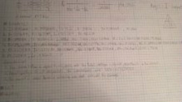
1. State two rules for the voltage and current in a series circuit.
-The current flow is equal to all parts and the total voltage is divided proportionally to the resistors
2. State two rules for the voltage and current in a parallel circuit.
-Voltage is equal to all parts and the current is found by [1/(1/R1)+(1/R2)+(1/R3)...]
3. If you remove a single bulb from an inexpensive string of Christmas tree lights, all of the lights in the entire string will go off. Are the bulbs connected in series or parallel? Explain.
-The circuit is series because removing one bulb cuts of the the current. aka it can't complete the circuit without it.
Have you ever used a calculator to add some numbers, looked at the answer, and realized that it was wrong? How did you know that the answer was incorrect? The calculator gave you an answer; why did you not trust it? You knew the answer was wrong because you understand the fundamentals of mathematics. Your instinct told you that the answer could not be correct.
The same is true for circuit analysis. Throughout this course you will be using a Circuit Design Software to test the circuits that you design. This software will always give an answer, right or wrong. The only way that you will be able to rely on these answers is if you have an understanding of the laws of circuit analysis. You must develop the same instinct for circuit behavior that you have for mathematics.
In this activity you will gain experience applying Ohm’s Law and Kirchhoff’s Voltage and Current Laws to solve simple series and parallel circuits.
Conclusion
1. State two rules for the voltage and current in a series circuit.
-The current flow is equal to all parts and the total voltage is divided proportionally to the resistors
2. State two rules for the voltage and current in a parallel circuit.
-Voltage is equal to all parts and the current is found by [1/(1/R1)+(1/R2)+(1/R3)...]
3. If you remove a single bulb from an inexpensive string of Christmas tree lights, all of the lights in the entire string will go off. Are the bulbs connected in series or parallel? Explain.
-The circuit is series because removing one bulb cuts of the the current. aka it can't complete the circuit without it.
1.2.3
As much fun as it is to analyze circuits by hand, the process becomes tedious as circuits grow in size and complexity. This is where Circuit Design Software (CDS) comes to the rescue. As the name implies, the CDS is a software tool that can be used to enter and simulate analog and digital circuit designs.
As with most computer applications, the CDS handles the mundane and repetitive tasks associated with analyzing circuits, allowing the designer (you) to concentrate on producing quality and creative designs.
In this activity you will gain experience using the Circuit Design Software to analyze simple analog circuits. In future activities we will use the CDS to analyze digital circuits as well. The circuits analyzed are some of the same circuits that were analyzed by hand in Activity 1.2.2. Thus, the theoretical and simulation results can be compared.
Conclusion
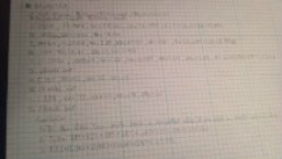
1. It should be obvious that using a CDS to analyze circuits is far easier than performing the calculations by hand. Yet, being able to perform these calculations by hand is still an important skill for a circuit designer. Why?
-In the field you won't have a computer also if you need a simple circuit done its easy to do by hand
2. Using the results from step (3) of the procedure, verify Kirchhoff’s Voltage Law.
-Take VR1+VR2+VR3+VR4=.67+2.47+.819+2.053=6V
3. Using the results from step (5) of the procedure, verify Kirchhoff’s Current Law.
-1/(1/2.7K)+(1/10k)+(1/3.3k)+(1/8.2k)=5.375k
As much fun as it is to analyze circuits by hand, the process becomes tedious as circuits grow in size and complexity. This is where Circuit Design Software (CDS) comes to the rescue. As the name implies, the CDS is a software tool that can be used to enter and simulate analog and digital circuit designs.
As with most computer applications, the CDS handles the mundane and repetitive tasks associated with analyzing circuits, allowing the designer (you) to concentrate on producing quality and creative designs.
In this activity you will gain experience using the Circuit Design Software to analyze simple analog circuits. In future activities we will use the CDS to analyze digital circuits as well. The circuits analyzed are some of the same circuits that were analyzed by hand in Activity 1.2.2. Thus, the theoretical and simulation results can be compared.
Conclusion
1. It should be obvious that using a CDS to analyze circuits is far easier than performing the calculations by hand. Yet, being able to perform these calculations by hand is still an important skill for a circuit designer. Why?
-In the field you won't have a computer also if you need a simple circuit done its easy to do by hand
2. Using the results from step (3) of the procedure, verify Kirchhoff’s Voltage Law.
-Take VR1+VR2+VR3+VR4=.67+2.47+.819+2.053=6V
3. Using the results from step (5) of the procedure, verify Kirchhoff’s Current Law.
-1/(1/2.7K)+(1/10k)+(1/3.3k)+(1/8.2k)=5.375k
1.2.5
Even though this is a course in digital electronics, it is important to understand that the world around us is analog. Virtually everything that can be designed with digital electronics is used to either control or monitor something in the world around us, and this world is analog. Thus, to be an effective designer of digital electronics, it is important for you to understand the characteristics of both analog and digital signals.
In this activity you will examine several analog and digital signals to determine their amplitude, period, and frequency. Additionally, you will gain experience using the oscilloscope within the Circuit Design Software (CDS).
Conclusion
1. List the characteristic that makes a digital signal different from an analog signal.
-digital signal is ON or OFF while analog signals are ranged
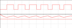
2. In the diagram shown below, label the parts of the analog signal.
-A. amplitude (peak) B. amplitude (peak to Peak) C. period
3. In the diagram shown below, label the parts of the digital signal.
-A. amplitude B.High time C. period D.low time E. rising edge F. falling edge
4. What are the two standard voltage levels that are acceptable for a digital signal?
-5Volts (ON) or 0Vlots (OFF)
Even though this is a course in digital electronics, it is important to understand that the world around us is analog. Virtually everything that can be designed with digital electronics is used to either control or monitor something in the world around us, and this world is analog. Thus, to be an effective designer of digital electronics, it is important for you to understand the characteristics of both analog and digital signals.
In this activity you will examine several analog and digital signals to determine their amplitude, period, and frequency. Additionally, you will gain experience using the oscilloscope within the Circuit Design Software (CDS).
Conclusion
1. List the characteristic that makes a digital signal different from an analog signal.
-digital signal is ON or OFF while analog signals are ranged
2. In the diagram shown below, label the parts of the analog signal.
-A. amplitude (peak) B. amplitude (peak to Peak) C. period
3. In the diagram shown below, label the parts of the digital signal.
-A. amplitude B.High time C. period D.low time E. rising edge F. falling edge
4. What are the two standard voltage levels that are acceptable for a digital signal?
-5Volts (ON) or 0Vlots (OFF)
1.2.6
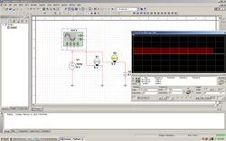
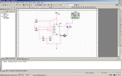
The 555 Timer oscillator is one of the most common circuits used in introductory electronics. It is a favorite among beginners because of its low cost and ease of design. These are precisely the same reasons the 555 Timer is used in the Board Game Counter design.
In this activity you will simulate and build a 555 Timer oscillator. You will observe the effect that varying the value of its resistor and capacitor values has on the oscillation frequency and duty cycle.
Conclusion
1. What effect did varying the RA have on the frequency and duty cycle?
-Rising the RA, lowers the frequency and ups the duty cycle
2. What effect did varying the RB have on the frequency and duty cycle?
-Rising the RB, lowers the frequency and duty cycle
3. What effect did varying the C have on the frequency and duty cycle?
-Rising the C, lowers the frequency and ups the duty cycle
1.2.7
The field of analog electronics is a unique discipline, distinct from the study of digital electronics. We have only scratched the surface of what you would learn if you continued your studies in this area. This project will be the last activity in our brief journey into the world of analog electronics.
In this activity you will use the Circuit Design Software to build and test the complete analog section of the Board Game Counter design.
Conclusion
1. When you press the push button of the Board Game Counter, the 555 Timer oscillates at approximately 65 Hz. It you want the oscillation to start at 100Hz, what value would you apply to C2?
-The value would be C2 is 723.076
2. The values of R8 & C1 determine the time from when the push button is released to when the oscillation stops. If you wanted to lengthen this time period, what changes would you make to one or both of these components? Explain.
-By increasing the value of C1
